
Soft finish cct for LNK3209 Buck
Posted by: treez
on
Hi,
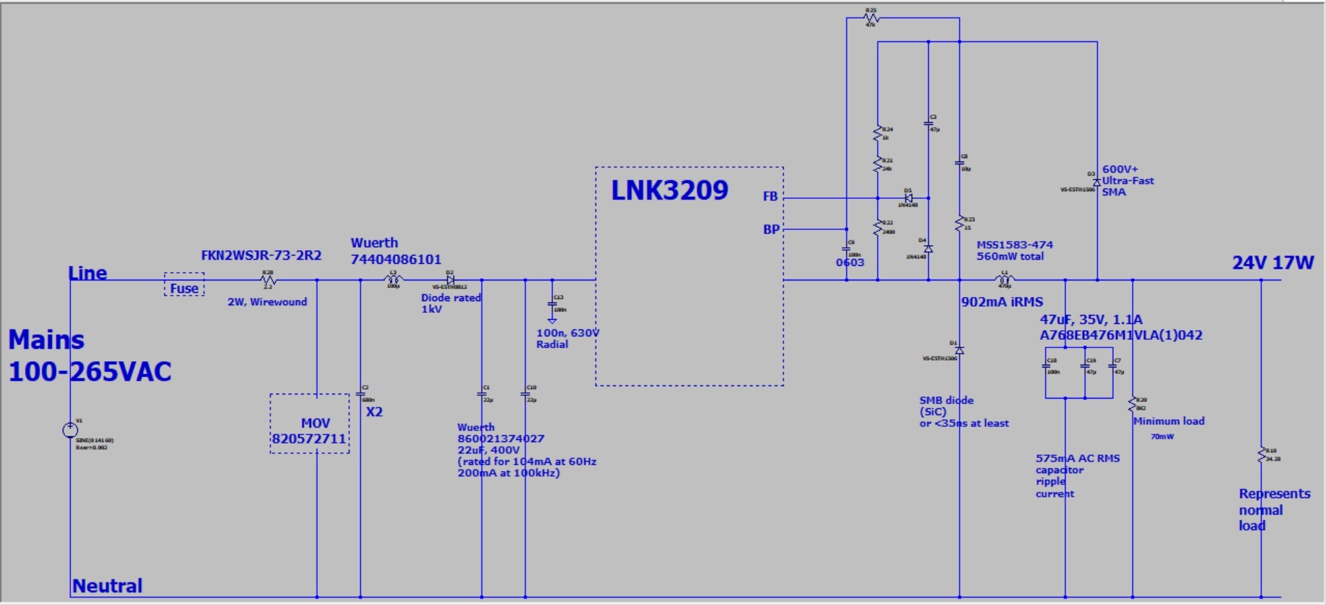
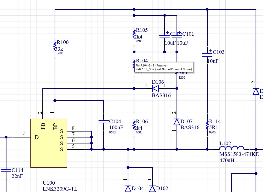
AN-70 says a cap may be needed across upper divider res in LNK3209, to stop it dropping out at startup.....they say up to 47uF...and that it may interfere with control...so why not do it like the "soft finish" cct with two diodes, that power integrations always used to recommend?
Soft finish as in the attached.
Files
| Attachment | Size |
|---|---|
| Buck LNK3209 with soft finish.jpg | 174.53 KB |
| lnk3902 with soft finish_0.jpg | 199.76 KB |
Hi treez,
The soft-finish circuit is generally mentioned in AN-43 which is the design guide for power supplies using TOPSwitch-HX.
Soft finish is used to provide the feedback signal at startup in order to prevent output from overshooting.
This is usually implemented for designs with high output capacitance or when the load delivered is high.
The circuit attached is taken from AN-43 (Figure 25). C20, D9 and R16 act as a soft finish circuit. As explained in the AN-43 document: "As the output voltage starts rising, current flows through the optocoupler diode inside U2A, resistor R13 and diode D9 to charge capacitor C20. This provides feedback to the primary circuit. The current in the optocoupler diode U2A gradually decreases as the capacitor C20 becomes charged and the control amplifier IC U3 becomes operational." C20 does not affect the feedback circuit after startup as it is is maintained charged by R16 and blocked by D9.
For designs using LinkSwitch-TN2, the purpose of the soft-finish circuit is no longer needed as the devices applies a soft start feature during startup or auto-restart. Soft start temporarily reduces the switching frequency of the device, effectively preventing overshoot as the output gradually increases over time. The use of the soft start capacitor in this case is to prevent the unit from auto restarting. This happens when the FB pin is not pulled high for 50 ms. The soft start capacitor lowers the voltage on the upper divider resistor of the feedback circuit during startup, effectively delivering higher current (> 49 µA) to the FB pin. Since this capacitor is always connected to the feedback circuit, it can affect response of the power supply when regulating the output.
In the circuits you provided, the goal seems to be that the soft start capacitor is to be effectively disconnected after startup. However, it has to be noted that the reference of the feedback circuit (S pin of the LNK3209) does not have a fixed voltage compared to the output. When the switch turns on, the reference is practically equal to the input voltage. This means that the diode D3 will turn off as the output voltage is lower than the supply voltage. The soft start capacitor will then form a loop with the divider resistors and diode D4/D107, which will conduct during this period. During turn on time, the capacitor is discharging. During turn off time, it will then be supplied again by the output and D5/D106 turns on as well. This means that the capacitor will still have an effect on the feedback circuit. Removing D4/D107 however will remove any discharge path for the capacitor during shut down.
With that said, the PIXls design spreadsheet which is part of the PI Expert™ design software suite can provide the necessary capacitance needed for the design. You can verify it by measuring the output ripple under different operating conditions and checking for the switching waveforms.
I hope I have answered your question adequately. Thank you for using PI Forum.